For drilling vs helical milling on a desktop CNC router, start with the hole you need. A suitable drill can be a practical choice for repeated standard round holes. A ramp-capable milling cutter can offer more diameter flexibility when the opening, depth, chip space and machine setup support it. Neither method automatically delivers a finished locating fit.
A small panel can reasonably use both routes. Its repeated fastener-clearance holes may favor a drill, while a separate larger opening or recess deserves its own evaluation. Avoiding one tool change is not a sufficient reason to choose an unsuitable operation.
Creating a hole, enlarging it and finishing it are separate jobs
In axial drilling, the drill advances along its axis. With a conventional single-diameter twist drill, the tool size establishes the nominal hole size; that does not mean the measured result will exactly equal the number on the shank. Tool condition, material, entry, holding and machine behavior still affect the hole.
Helical milling combines circular movement with axial advance. The cutter follows a circle while descending at a planned pitch. That differs from circular milling around an existing opening at a constant Z level. Both involve a circular path, but the material encountered and the work done by the cutter are different.
Sandvik Coromant's hole-and-pocket guide separates creating openings from widening existing holes. It identifies diameter flexibility, tool-magazine space and some flat-bottomed blind-hole requirements among reasons to consider milling. Its industrial examples are not cutting recipes or production thresholds for a desktop router.
A final bore adds another question: what must the finished surface do? A hole that merely lets a fastener pass has a different purpose from one that locates a component closely. The first operation can leave work for a subsequent sizing or finishing process. Calling an opening “milled” does not establish its size, position, form or surface quality.
A flexible diameter still needs room for the cutter
For a simple cylindrical internal contour, the nominal tool-center path diameter is the intended hole diameter minus the cutter diameter. As a geometry example only, a 20 mm circle made with a 6 mm cylindrical cutter has a nominal 14 mm tool-center circle. This is not an entry plan, a feed calculation or a recommended hole-and-tool combination.
The drawing can therefore show a circle that the machine can trace while the proposed cutter remains unsuitable for making it from solid stock. The end geometry must support the entry, the actual minimum hole size must suit the tool, and the helix must stay within its permitted ramping application. A tool being smaller than the finished hole is only the beginning of that assessment.
Seco's helical-interpolation guidance emphasizes ramp-capable tools and adequate space for machining and chip evacuation. A cutter that is too large relative to the opening can leave insufficient room. Use the actual toolmaker's application data rather than a generic ratio, a stock CAM default or the fact that a helical path can be displayed.
Existing cleared space changes the assessment. A suitable tool entering an already open region does not encounter the same material as it would while creating that opening from solid. Conversely, a small pilot hole does not necessarily clear every noncutting area or provide enough space for a proposed path. Confirm what stock remains, not simply whether a hole exists.

Depth and the bottom shape can change an otherwise sensible choice
A shallow opening and a deep hole of the same diameter are not equivalent operations. Reach, cutting length, chip removal and clearance around the holder change as the feature gets deeper. An end mill that reaches the drawing's floor may still leave an unsuitable engagement or chip path.
Drilling also needs a tool and process intended for the actual depth and material. Do not interpret a drill's long overall length as usable cutting depth, or assume that a spindle's available speed range suits every drill and material combination. Match operating conditions to the installed machine and exact tool.
A blind hole requires attention to what “depth” means on the drawing. A conventional pointed drill leaves a conical end region rather than automatically producing a flat floor across the full diameter. If a component needs a flat-bottomed recess, that is a finished-feature requirement to plan, not a cosmetic difference to ignore.
A suitable milling operation may be useful for that floor, but not every end mill and entry mode can create it from solid. The route might combine an opening operation with a separate finishing operation. For a through-hole, evaluate the exit, backing and clearance below the stock instead; the operation must not unexpectedly reach the machine table or fixture.
Chip control belongs in both plans. Follow the equipment and toolmaker's supported method for the material and setup. Industrial advice about through-spindle coolant or air systems does not authorize a retrofit or improvised fluid use on a desktop machine. Never reach into a moving operation to clear chips by hand.
Assign the route to the feature, not to the entire panel
Consider a hypothetical, non-safety-critical aluminum instrument mounting panel. It has a group of identical standard fastener-clearance holes and one larger circular recess for a component. The example is a planning comparison, not a tested ED1 part.
The repeated holes may suit an appropriate drill because the same nominal diameter is needed at several positions. If the drill, material, spindle conditions and holding arrangement are suitable, there is no requirement to interpolate them simply because the machine also performs milling.
The recess asks a different question. Its diameter may not correspond to a drill already available, its floor may need to be flat, and several versions of the panel may use different recess diameters. A suitable milling cutter can potentially serve those variants without a dedicated drill for each size. That flexibility has value only if the cutter can enter, reach, evacuate chips and produce the required geometry.
Now change the recess into a close locating bore. The initial opening route no longer completes the decision. Size, roundness, position and finish need appropriate inspection, and a further finishing process may be required. A single caliper reading across the mouth does not establish every one of those characteristics.
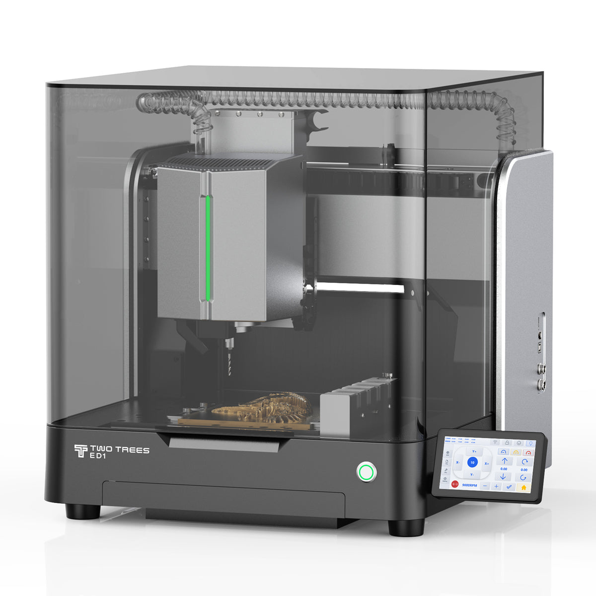
For a desktop CNC router such as the enclosed ED1, evaluate that complete panel setup rather than assuming that programmed motion guarantees the result. Stock, workholding, tool and holder clearance, material guidance and the machine's supported operating conditions all have to agree.
Compare the complete route before removing a tool change
For one panel, a milling cutter already installed for a suitable operation may reduce the need for another tool. For many repeated standard holes, the work saved by a suitable drill may outweigh that change. The comparison includes preparation, holding, entry, machining, finishing and inspection—not only the number of tools in the program.
When choosing a CNC router for aluminum work, the same principle applies to the platform itself. An enclosure or spindle-power label is not evidence that any drill, hole depth or material grade is supported. Begin with the actual feature and operating requirements, then evaluate a machine against them.
The TwoTrees CNC router bits and end mills collection provides a route to compare tool families. For CNC router bits for aluminum, check the exact tool's intended material and operation, shank, cutting geometry and reach. A listing in the same collection does not make drills and end mills interchangeable, and a drill should not be used as a side-cutting end mill.
Before setup, tool changes or hands-on inspection, stop and safely isolate the equipment according to its instructions. Secure the stock and use the specified protective measures, chip control and supervision. Review the actual program and setup before processing; a plausible circle on screen is not a qualification of the cut.
For the hypothetical panel, use a suitable drill route for the repeated clearance holes and evaluate the larger recess separately. Choose helical milling where its flexibility meets the actual entry, depth and clearance conditions. If the finished feature needs more than the initial opening can provide, keep the necessary finishing and inspection in the plan rather than declaring the hole complete because the toolpath has ended.